
You must connect your Arlo Essential Wired Video Doorbell to a 2.4 GHz Wi-Fi network. The Arlo Essential Wired Video Doorbell replaces your existing doorbell.
#WIRED DOORBELL DIAGRAM INSTALL#
For a detailed guide to installing your Power Kit, visit: How do I install the Arlo Power Kit for my Arlo Essential Video Doorbell Wired?
#WIRED DOORBELL DIAGRAM FREE#
Properly functioning connection points and wiring should be kept clean and free of dust, rust, and other debris. Lastly, it is important to regularly inspect and clean the wiring and switches. The switch and transformer should also be tested periodically to ensure that they are working. The terminals should be insulated properly, and all wires should be properly secured. The main components of the system should be tested after installation to ensure that they are functioning properly. Installing and Maintaining a 4 Wire Doorbell System When installing a 4 wire doorbell system, it is important to follow the instructions in the wiring diagram precisely. As with any wiring installation, it is important to read and understand the instructions before beginning the installation process. The diagram should describe the purpose of each wire, the direction it goes, how it is clamped and secured, and any applicable safety precautions.

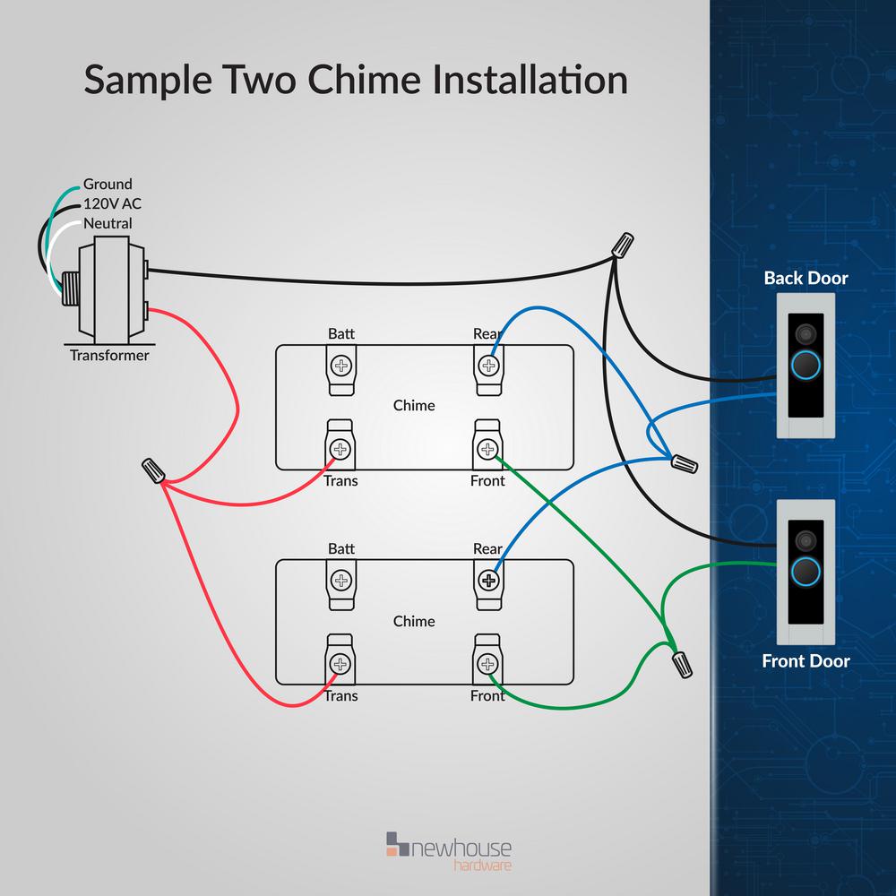
Terminal connectors for the chime mechanism.Ground and neutral connections for the power supply.Connections for additional colored wires (if applicable).White and black wires running between the switch and the transformer.A typical diagram will show the following: Understanding the 4 Wire Doorbell Wiring Diagram Most 4 wire doorbell wiring diagrams show the wiring between the switch and the transformer, along with the power source. Depending on the type of doorbell system being used, additional colored wires may be necessary. The black wire is the “hot” or “live” wire, while the white wire is the return. The two connecting wires, usually black and white, run between the transformer and the switch. The switch is used to send a signal to the transformer, which converts electricity from the power supply into a low voltage current that is sent out to the bell or chime mechanism.

The two wiring locations include a switch inside the house, and a transformer outside. Each component must be connected and secured properly in order for the system to function reliably. Components of a 4 Wire Doorbell System A 4 wire doorbell system consists of four basic components: two wiring locations, two connecting wires, a power supply, and a bell or chime mechanism. Here, we will review some of the key components of 4 wire doorbell wiring diagrams, explain their purpose, and discuss the steps involved in successful installation and maintenance. This article will focus on 4-wire doorbell wiring diagrams, which are used with most conventional doorbell systems. Doorbells come in different varieties, and each type requires a unique wiring diagram. For safety and convenience, it also helps to understand doorbell wiring diagrams, as they provide insight into what type of components are required, how they need to be connected, and the importance of proper grounding and insulation. Understanding 4 Wire Doorbell Wiring Diagrams Wiring a doorbell correctly is an important part of installing and maintaining a visitor notification system.


 0 kommentar(er)
